 -->
-->Debugging Tools for Windows supports kernel debugging over a null-modem cable. Null-modem cables are serial cables that have been configured to send data between two serial ports. Do not confuse null-modem cables with standard serial cables. Standard serial cables do not connect serial ports to each other. For information about how null-modem cables are wired, see Null-Modem Cable Wiring.
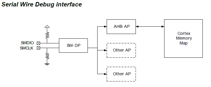
The SW Device section displays one or more debug targets connected through the Serial Wire interface. The IDCODE and Device Name are displayed automatically for each device. AP field specifies the identifier of the Access Port in multi-core devices with a single Debug Port (DP). The Access Port specification depends on the Arm Debug Interface (ADI) supported in the device.
The computer that runs the debugger is called the host computer, and the computer being debugged is called the target computer.
Setting Up the Target Computer
Important
Before using bcdedit to change boot information you may need to temporarily suspend Windows security features such as BitLocker and Secure Boot on the test PC.You can re-enable Secure Boot once you’re done debugging and you’ve disabled kernel debugging.
On the target computer, open a Command Prompt window as Administrator, and enter the following commands, where n is the number of the COM port used for debugging on the target computer, and rate is the baud rate used for debugging:
Droid x sbf file 2.2. File contains backup of mobile phone settings, MMS and SMS messages, phone book, call logs and applications.SBF backup files are stored only on SD memory card in databackup directory.
bcdedit /debug on
bcdedit /dbgsettings serial debugport:nbaudrate:rate
Note The baud rate must be the same on the host computer and target computer. The recommended rate is 115200.
Reboot the target computer.
Starting the Debugging Session
Connect the null-modem cable to the COM ports that you have chosen for debugging on the host and target computers.
Using WinDbg
On the host computer, open WinDbg. On the File menu, choose Kernel Debug. In the Kernel Debugging dialog box, open the COM tab. In the Baud rate box, enter the rate you have chosen for debugging. In the Port box, enter COMn where n is the COM port number you have chosen for debugging on the host computer. Click OK.
You can also start a session with WinDbg by entering the following command in a Command Prompt window; n is the number of the COM port used for debugging on the host computer, and rate is the baud rate used for debugging:
windbg -k com:port=COMn,baud=rate
Using KD
On the host computer, open a Command Prompt window, and enter the following command, where n is the number of the COM port used for debugging on the host computer, and rate is the baud rate used for debugging:
kd -k com:port=COMn,baud=rate
Using Environment Variables
On the host computer, you can use environment variables to specify the COM port and the baud rate. Then you do not have to specify the port and baud rate each time you start a debugging session. To use environment variables to specify the COM port and baud rate, open a Command Prompt window and enter the following commands, where n is the number of the COM port used for debugging on the host computer, and rate is the baud rate used for debugging:
- set _NT_DEBUG_PORT=COMn
- set _NT_DEBUG_BAUD_RATE=rate
To start a debugging session, open a Command Prompt window, and enter one of the following commands:
- kd
- windbg
Troubleshooting Tips for Debugging over a Serial Cable
Specify correct COM port on both host and target
Determine the numbers of the COM ports you are using for debugging on the host and target computers. For example, suppose you have your null-modem cable connected to COM1 on the host computer and COM2 on the target computer.
On the target computer, open a Command Prompt window as Administrator, and enter bcdedit /dbgsettings. If you are using COM2 on the target computer, the output of bcdedit should show debugport 2.
On the host computer, specify the correct COM port when you start the debugger or when you set environment variables. If you are using COM1 on the host computer, use one of the following methods to specify the COM port.
- In WinDbg, in the Kernel Debugging dialog box, enter COM1 in the Port box.
- windbg -k com:port=COM1, ..
- kd -k com:port=COM1, ..
- set _NT_DEBUG_PORT=COM1
Baud rate must be the same on host and target
The baud rate used for debugging over a serial cable must be set to the same value on the host and target computers. For example, suppose you have chosen a baud rate of 115200.
On the target computer, open a Command Prompt window as Administrator, and enter bcdedit /dbgsettings. The output of bcdedit should show baudrate 115200.
On the host computer, specify the correct baud rate when you start the debugger or when you set environment variables. Use one of the following methods to specify a baud rate of 115200.
- In WinDbg, in the Kernel Debugging dialog box, enter 115200 in the Baud rate box.
- windbg -k .., baud=115200
- kd -k .., baud=115200
- set _NT_DEBUG_BAUD_RATE=115200
Null Modem Cable Wiring
The following tables show how null-modem cables are wired.
9-pin connector
| Connector 1 | Connector 2 | Signals |
|---|---|---|
| 2 | 3 | Tx - Rx |
| 3 | 2 | Rx - Tx |
| 7 | 8 | RTS - CTS |
| 8 | 7 | CTS - RTS |
| 4 | 1+6 | DTR - (CD+DSR) |
| 1+6 | 4 | (CD+DSR) - DTR |
| 5 | 5 | Signal ground |
25-pin connector
| Connector 1 | Connector 2 | Signals |
|---|---|---|
| 2 | 3 | Tx - Rx |
| 3 | 2 | Rx - Tx |
| 4 | 5 | RTS - CTS |
| 5 | 4 | CTS - RTS |
| 6 | 20 | DSR - DTR |
| 20 | 6 | DTR - DSR |
| 7 | 7 | Signal ground |
Signal Abbreviations
| Abbreviation | Signal |
|---|---|
| Tx | Transmit data |
| Rx | Receive data |
| RTS | Request to send |
| CTS | Clear to send |
| DTR | Data terminal ready |
| DSR | Data set ready |
| CD | Carrier detect |
Additional Information
For complete documentation of the bcdedit command, see BCDEdit Options Reference.
Related topics
Serial Wire Debug Bus
Serial Wire Debug bus Description

SWD bus: [Serial Wire Debug], defines a point-to-point two wire serial bus developed by ARM in 2004.
In some cases the Serial Wire Debug uses the acronym [SW-DB] when referring to the Serial Wire Debug interface.
SWD is designed to replace the normal 5-pin JTAG port with a clock and single bi-directional data pin, providing all the normal JTAG debug and test functionality. SWD avoids the need to use scan chains for debug.
SWD uses an ARM standard bi-directional wire protocol, defined in the ARM Debug Interface, to pass data to and from the debugger and the target system. The SWD bus is a standard interface for ARM-based devices.
The new multi-drop SWD released in 2009 is fully backwards compatible with the previous version, retaining existing single point-to-point host equipment connections, and enables a device to power down completely while that device is not selected, reducing power consumption. The ARM multi-drop SWD has been designed to be fully interoperable with the recently announced IEEE 1149.7 standard.
Seems like the names Serial Wire Debug and Single Wire Debug are interchangeable.
Related posting; Design-For-Testability.
ARM or Advanced RISC Machine is a RISC processor currently used by a number of different companies.
Engineering Design tags: SWD Specification, IC Interface standard Data Bus, Physical or electrical Interface, and circuit Topology.
Navigation >Engineering Home >Electrical Interface Buses >IC-to-IC Buses > Serial Wire Debug.
| Home | |||||||
| Distributors | Components | Equipment | Software | Standards | Buses | Design | Reference |
Copyright © 1998 - 2016 All rights reserved Larry Davis
- Author: admin
- Category: Category
Debugging Tools for Windows supports kernel debugging over a null-modem cable. Null-modem cables are serial cables that have been configured to send data between two serial ports. Do not confuse null-modem cables with standard serial cables. Standard serial cables do not connect serial ports to each other. For information about how null-modem cables are wired, see Null-Modem Cable Wiring.
The SW Device section displays one or more debug targets connected through the Serial Wire interface. The IDCODE and Device Name are displayed automatically for each device. AP field specifies the identifier of the Access Port in multi-core devices with a single Debug Port (DP). The Access Port specification depends on the Arm Debug Interface (ADI) supported in the device.
The computer that runs the debugger is called the host computer, and the computer being debugged is called the target computer.
Setting Up the Target Computer
Important
Before using bcdedit to change boot information you may need to temporarily suspend Windows security features such as BitLocker and Secure Boot on the test PC.You can re-enable Secure Boot once you’re done debugging and you’ve disabled kernel debugging.
On the target computer, open a Command Prompt window as Administrator, and enter the following commands, where n is the number of the COM port used for debugging on the target computer, and rate is the baud rate used for debugging:
Droid x sbf file 2.2. File contains backup of mobile phone settings, MMS and SMS messages, phone book, call logs and applications.SBF backup files are stored only on SD memory card in databackup directory.
bcdedit /debug on
bcdedit /dbgsettings serial debugport:nbaudrate:rate
Note The baud rate must be the same on the host computer and target computer. The recommended rate is 115200.
Reboot the target computer.
Starting the Debugging Session
Connect the null-modem cable to the COM ports that you have chosen for debugging on the host and target computers.
Using WinDbg
On the host computer, open WinDbg. On the File menu, choose Kernel Debug. In the Kernel Debugging dialog box, open the COM tab. In the Baud rate box, enter the rate you have chosen for debugging. In the Port box, enter COMn where n is the COM port number you have chosen for debugging on the host computer. Click OK.
You can also start a session with WinDbg by entering the following command in a Command Prompt window; n is the number of the COM port used for debugging on the host computer, and rate is the baud rate used for debugging:
windbg -k com:port=COMn,baud=rate
Using KD
On the host computer, open a Command Prompt window, and enter the following command, where n is the number of the COM port used for debugging on the host computer, and rate is the baud rate used for debugging:
kd -k com:port=COMn,baud=rate
Using Environment Variables
On the host computer, you can use environment variables to specify the COM port and the baud rate. Then you do not have to specify the port and baud rate each time you start a debugging session. To use environment variables to specify the COM port and baud rate, open a Command Prompt window and enter the following commands, where n is the number of the COM port used for debugging on the host computer, and rate is the baud rate used for debugging:
- set _NT_DEBUG_PORT=COMn
- set _NT_DEBUG_BAUD_RATE=rate
To start a debugging session, open a Command Prompt window, and enter one of the following commands:
- kd
- windbg
Troubleshooting Tips for Debugging over a Serial Cable
Specify correct COM port on both host and target
Determine the numbers of the COM ports you are using for debugging on the host and target computers. For example, suppose you have your null-modem cable connected to COM1 on the host computer and COM2 on the target computer.
On the target computer, open a Command Prompt window as Administrator, and enter bcdedit /dbgsettings. If you are using COM2 on the target computer, the output of bcdedit should show debugport 2.
On the host computer, specify the correct COM port when you start the debugger or when you set environment variables. If you are using COM1 on the host computer, use one of the following methods to specify the COM port.
- In WinDbg, in the Kernel Debugging dialog box, enter COM1 in the Port box.
- windbg -k com:port=COM1, ..
- kd -k com:port=COM1, ..
- set _NT_DEBUG_PORT=COM1
Baud rate must be the same on host and target
The baud rate used for debugging over a serial cable must be set to the same value on the host and target computers. For example, suppose you have chosen a baud rate of 115200.
On the target computer, open a Command Prompt window as Administrator, and enter bcdedit /dbgsettings. The output of bcdedit should show baudrate 115200.
On the host computer, specify the correct baud rate when you start the debugger or when you set environment variables. Use one of the following methods to specify a baud rate of 115200.
- In WinDbg, in the Kernel Debugging dialog box, enter 115200 in the Baud rate box.
- windbg -k .., baud=115200
- kd -k .., baud=115200
- set _NT_DEBUG_BAUD_RATE=115200
Null Modem Cable Wiring
The following tables show how null-modem cables are wired.
9-pin connector
| Connector 1 | Connector 2 | Signals |
|---|---|---|
| 2 | 3 | Tx - Rx |
| 3 | 2 | Rx - Tx |
| 7 | 8 | RTS - CTS |
| 8 | 7 | CTS - RTS |
| 4 | 1+6 | DTR - (CD+DSR) |
| 1+6 | 4 | (CD+DSR) - DTR |
| 5 | 5 | Signal ground |
25-pin connector
| Connector 1 | Connector 2 | Signals |
|---|---|---|
| 2 | 3 | Tx - Rx |
| 3 | 2 | Rx - Tx |
| 4 | 5 | RTS - CTS |
| 5 | 4 | CTS - RTS |
| 6 | 20 | DSR - DTR |
| 20 | 6 | DTR - DSR |
| 7 | 7 | Signal ground |
Signal Abbreviations
| Abbreviation | Signal |
|---|---|
| Tx | Transmit data |
| Rx | Receive data |
| RTS | Request to send |
| CTS | Clear to send |
| DTR | Data terminal ready |
| DSR | Data set ready |
| CD | Carrier detect |
Additional Information
For complete documentation of the bcdedit command, see BCDEdit Options Reference.
Related topics
Serial Wire Debug Bus
Serial Wire Debug bus Description
SWD bus: [Serial Wire Debug], defines a point-to-point two wire serial bus developed by ARM in 2004.
In some cases the Serial Wire Debug uses the acronym [SW-DB] when referring to the Serial Wire Debug interface.
SWD is designed to replace the normal 5-pin JTAG port with a clock and single bi-directional data pin, providing all the normal JTAG debug and test functionality. SWD avoids the need to use scan chains for debug.
SWD uses an ARM standard bi-directional wire protocol, defined in the ARM Debug Interface, to pass data to and from the debugger and the target system. The SWD bus is a standard interface for ARM-based devices.
The new multi-drop SWD released in 2009 is fully backwards compatible with the previous version, retaining existing single point-to-point host equipment connections, and enables a device to power down completely while that device is not selected, reducing power consumption. The ARM multi-drop SWD has been designed to be fully interoperable with the recently announced IEEE 1149.7 standard.
Seems like the names Serial Wire Debug and Single Wire Debug are interchangeable.
Related posting; Design-For-Testability.
ARM or Advanced RISC Machine is a RISC processor currently used by a number of different companies.
Engineering Design tags: SWD Specification, IC Interface standard Data Bus, Physical or electrical Interface, and circuit Topology.
Navigation >Engineering Home >Electrical Interface Buses >IC-to-IC Buses > Serial Wire Debug.
| Home | |||||||
| Distributors | Components | Equipment | Software | Standards | Buses | Design | Reference |
Copyright © 1998 - 2016 All rights reserved Larry Davis